set prompt = ‘%n@%M %/ %W/%D %T %h %# ‘
Category: Uncategorized
Best Articles to talking about Asynchronous reset synchronization and distribution – challenges and solutions
Multicycle path hold timing checks shift back by numbers
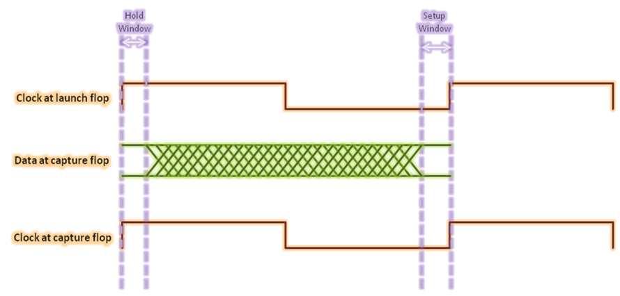
Basic Timing Check
https://vlsiuniverse.blogspot.com/2013/06/setup-and-hold-basics-of-timing-analysis.html
Tck->q + Tprop + Tsetup < Tperiod + Tskew
Tck->q + Tprop > Thold + Tskew
Data valid window = Clock period – Setup window – Hold window
Start of data valid window = Tlaunch + Thold
End of data valid window = Tlaunch + Tperiod – Tsetup
Setup slack = Tperiod – (Tck->q + Tprop + Tsetup – Tskew)
Hold slack = Tck->q + Tprop – Thold – Tskew
Mitigating setup violation: Thus, we can meet the setup requirement, if violating, by
- Decreasing clk->q delay of launching flop
- Decreasing the propagation delay of the combinational cloud
- Reducing the setup time requirement of capturing flop
- Increasing the skew between capture and launch clocks
- Increasing the clock period
Mitigating hold violation: We can meet the hold requirement by:
- Increasing the clk->q delay of launching flop
- Decreasing the hold requirement of capturing flop
- Decreasing clock skew between capturing clock and launching flip-flops
9’s compliment of a BCD number
9’s compliment is nothing but subracting the given no from 9.So using a 4 bit binary adder we can just subract the given binary no from 1001(i.e. 9).Here we can use the 2’s compliment method addition.
Minimum circuits to detect clockwise
The circle can rotate clockwise and back. Use minimum hardware to build a circuit to indicate the direction of rotating.?
2 sensors are required to find out the direction of rotating. They are placed like at the drawing. One of them is connected to the data input of D flip-flop,and a second one – to the clock input. If the circle rotates the way clock sensor sees the light first while D input (second sensor) is zero – the output of the flip-flop equals zero, and if D input sensor “fires” first – the output of the flip-flop becomes high. 
Clock Skew does not impact setup times, but setup slacks
FSM design without using adders
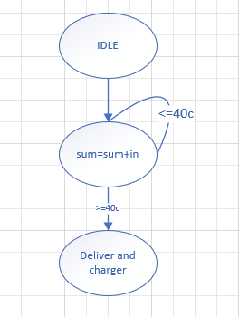
Q: A beverage machine can accept coin in 25c, 10c, and 5c. When the amount is more than 40c, deliver the beverage and charger. How to design the FSM without using adders?
Following diagram uses adder.
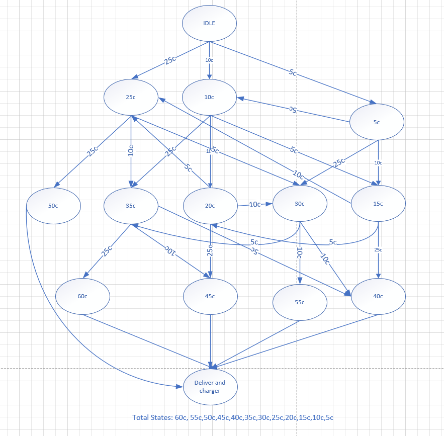
 Following does not.
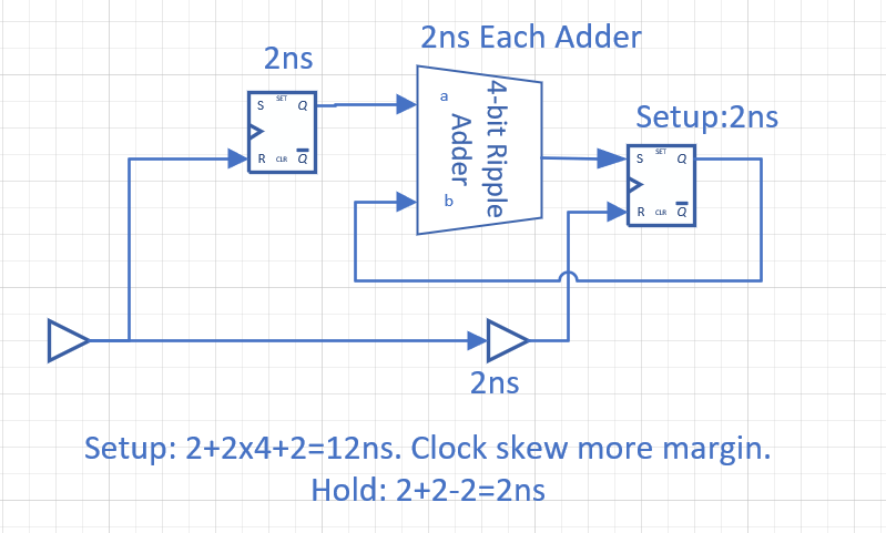
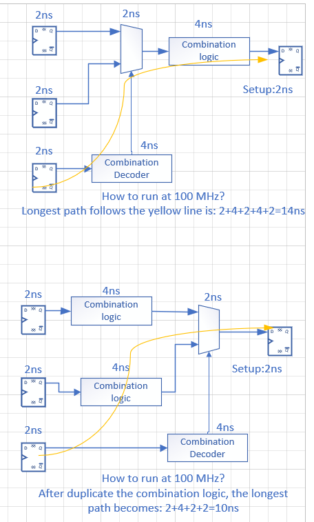
Duplicate combination logic to solve setup time violation
How to change the FIFO RAM to single port
As following diagram. Assume the input and output clock are unknown relationship.

One sample way is to add a small FIFO at and of the single port SRAM as following.

Another way is used two single port SRAM working as ping-pong buffers.
